
 中文版
中文版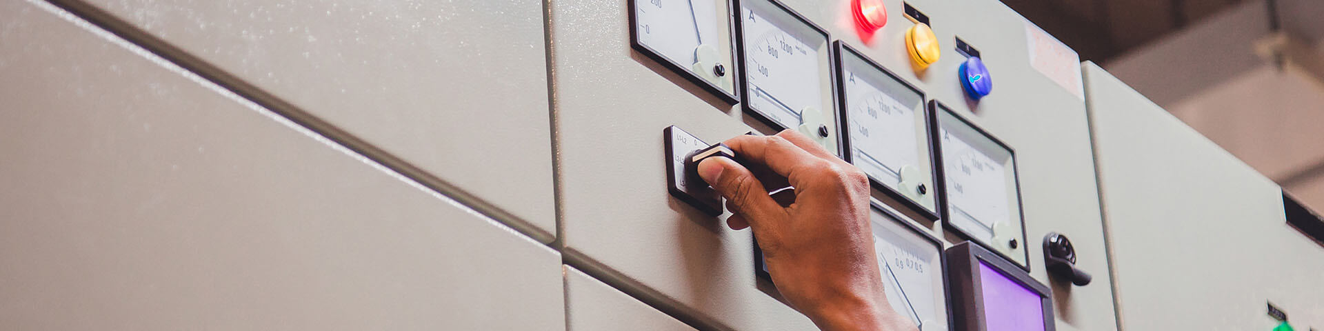
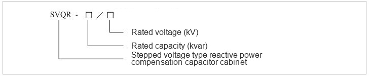
HZS-SVQR voltage regulating type reactive power substation reactive power automatic compensation capacitor cabinet
Product description
HZS-SVQR voltage regulating type reactive power substation reactive power automatic compensation capacitor cabinet is a kind of new substation reactive power automatic compensation capacitor cabinet equipment. It can be used in the power grid system and leads the trend of new technology in the industry. Compared with the traditional substation reactive power compensation capacitor cabinet equipment, this equipment adopts a new technical idea and breaks through the traditional reactive power compensation mode of grouping switching on and switching off the capacitors, which are composed of the circuit breakers, vacuum contactors and so on. This equipment does not make compensation for the reactive power by switching on and switching off the capacitors. However based on the principle that the capacitive reactive power output by the capacitor is proportional to the square of the terminal voltage in the reactive power compensation, it changes the terminal voltage of the stationary capacitor bankst hrough adjusting the output voltage of the voltage regulator. The purpose of carrying out fine compensation for the reactive power has been met.
The controller of the device adopts the advanced measurement and control technology. It can monitor and display the voltage, current, power factor, reactive power and other parameters of the system in real time and, at the same time, can adjust the control and protection parameters. According to the mode of controlling the voltage and the reactive power, the controller automatically adjusts the gear position of the on-load tap changer according to the changes in the voltage as well as the changes in the reactive power. In this way, the output voltage of the self coupling on-load voltage regulator can be changed. Because the capacitor banks are connected to the output side of the voltage regulator, and the input of the voltage regulator is connected to the bus or the circuit, with the changes in the voltage at the output end of the voltage regulator, the capacity for reactive power compensation outputted by the capacitor banks to the power grid system will change accordingly. The device can be used in a substation or in a distribution line so as to realize the automatic compensation for the large capacity reactive power at three voltage levels i.e. 6kV, 10kV and 35kV. This is also applicable to the substations and the distribution lines in the high altitude areas.
The equipment is mainly composed of the voltage regulator,the shunt capacitor banks, the controller and so on. The structure is simple and the functions are perfect; its installation is can be carried out with ease and convenience.
This product has overcome the technical problems that have been perplexing the power system for a long time, and provides a powerful technical guarantee for construction of the power grid. The product has obtained the national patent.
Product model
The range of capacity: when the voltage level is 6kv, the rated capacity of the capacitor is ≤6000kvar
When the voltage level is 10kv, the rated capacity of the capacitor is ≤ 12,500kvar
When the voltage level is 35kv, the rated capacity of capacitor is ≤ 36000kvar
Composition mechanism and working principle
The HZS-SVQR voltage regulation type reactive power automatic compensation capacitor cabinet is mainly composed of the primary part and the secondary part. The primary part mainly includes the isolation switch, the self-coupling voltage regulator, the series electric reactors (in an occasion where the harmonic is more severer, the reactors which has the required reactance rate is to be connected in series between the self coupling transformer voltage regulator and the capacitor banks), the power capacitor, the discharge coil, the lightning arrester, a fence, and the like.
The secondary part mainly includes the control panel (the controller and the manual operating system).
Compared with the other conventional compensation devices, the HZS-SVQR voltage regulation type reactive power automatic compensation capacitor cabinet does not make compensation for the reactive power through changing the capacitance value C. However the compensation for reactive power is realized by using the principle that the reactive power outputted by the capacitor bank in the reactive power compensation is proportional to the square of the terminal voltage, that is, Q=wCU².
Although only a capacitor bank with a fixed capacity is used in the whole equipment, the capacitance value of the capacitors is fixed in the process of compensation. However the reactive power which is outputted varies with the changes in the terminal voltage.
Composition
The automatic voltage regulator of the SVR line consists of three parts: the self coupling transformer, the on-load tap changer and the automatic controller. The whole coil of the self coupling transformer is divided into three parts: the series excitation coil, the shunt coil and the control coil. Among them, the series excitation coil is a winding with multiple taps, which are connected in series between the input and output through the different contacts on the on-load tap changer to change the tap positions. As a result, the ratio of transformation of the self coupling transformer is changed; achieving the purpose of adjusting the voltage; the shunt coil is the common winding of the self coupling transformer, which can generate the magnetic field for transmitting of the energy; the control coil provides the working power supply and sampling signal for the controller.
The on-load tap changer is a switch that can switch contacts under the loaded condition. In the automatic voltage regulator, the taps of the series winding are connected to the different contacts of the on-load tap changer; the output voltage can be changed by changing the contact points so as to adjust the ratio of transformation, consequently changing the output voltage of the transformer. The automatic controller is the core part of the whole equipment. It is mainly composed of the control chip in the single chip microcomputer, the display circuit, the keystroke circuit, the circuits of voltage sampling, current sampling, state input, communication port, control output and data storage and other circuits. The computer technology, electronic technology, military level control chip have been adopted, so the equipment has a high reliability, a strong anti-interference ability and it can be adapted to the outdoor harsh environment.
Product features
1: The advanced compensation technology
This equipment has broken through the traditional reactive power compensation method in which the circuit breakers and vacuum contactors are used to perform the grouped switching on and switching off of the capacitor banks. This has solved the problems of inrush current as well as the reburning overvoltage in the process of the switching on and switching off operations.
2: The real time tracking makes the compensation to be performed in a finer manner
Through changing the output voltage of the voltage regulator,the terminal voltage of the compensation capacitor can be changed, and then change the reactive power output of the device; the on-load tap changer is used to adjust the output voltage of the voltage regulator; the adjustment accuracy is high and the differences between the stages are small, which can reach the level seven or the level nine.As the result, the automatic tracking compensation for the reactive power can be carried out in a finer manner.
3: The operation is safe and reliable
In the process of running, the differential in the voltage regulation of the voltage regulator is small. In addition, the access of the transition resistance of the on-load tap changer and the leakage reactance of the voltage regulator itself, there is almost no inrush current which has been produced. As the result, the impact on the system has been reduced, the safe operation of the system is guaranteed, and the service life of the equipment has been extended.
4: The service life of the equipment has been improved
In the process of using the on-load tap changer to complete the switching, the capacitor is not cut off, which will greatly prolong the service life of the capacitor and the generation of operating overvoltage can be avoided.
5: The intelligent control
The device has high degree of automation. It is adaptable to all kinds of operation modes of the main transformer at a substation. It is equipped with a friendly man-machine interface. It has perfect protection functions; it has the capacitor overcurrent protection, the overvoltage protection, the zero sequence current protection, the voltage regulator gas and temperature protection as well as other protection functions. The equipment has such characteristics as simple operation and high reliability.
6: The local and remote monitoring is realized
The equipment has complete communication and data storage functions. It can collect the real-time data as well as the historical operation data of three-month. It can realize data transmission, local and remote monitoring through the wireless communication module and by using GPRS or CDMA and other communication methods.
7: It has a strong compatibility
This equipment is not only applicable to new substations, but also suitable for the transformation of the old substations. In the transformation of an old substation, only a voltage regulator will be needed to be connected between the circuit breaker and the capacitor bank of the traditional reactive power compensation device. Then the original manual type fixed reactive power compensation capacitor cabinet can be transformed into an automatic compensation capacitor cabinet with 9 levels of fine reactive power regulation. What’s more, the original compensation equipment at the substation, such as the switchgear, the reactor, the capacitor bank, the discharge coil, the isolation switch and so on, can continue to be used.
8: The cost performance of the equipment is high
With the same capacity, the cost of this equipment is only 20 - 30% of that of the static Var compensator (SVC).
Conditions of use
(1) Altitude: ≤ 2000m (in case that the equipment for a client is to be installed in a place which is above 2000m, this should be specially put forward when ordering)
(2) The ambient temperature: the maximum temperature is + 40 ℃; the minimum temperature is -35 ℃
(3) The anti-filth ability: Grade III
(4) The inclination: ≤ 3o
(5) The wind speed: not to be more than 35m/s
(6) The seismic level: As to the ground acceleration caused by earthquake, it should be less than 3m /S2 in the horizontal direction and should be less than 1.5m/s2 in the vertical direction
(7) The ambient conditions: There should be no obvious pollution and fire and explosion risks.
Table of main parameters
1. The parameters of the controller:
● Rated voltage of: AC/DC 220V
● Rated frequency: 50Hz
● Maximum power consumption: ≤ 30W
● Switch input: 21 channels of idle contact input
● Switch output: 12 channels
● Voltage analog input range: AC100 × (60% - 120%) V
● Current analog input range: 5 × (10% - 120%) A
● Measurement accuracy: level 0.5
● Anti-interference level: level 3, to be in accordance with the requirements in
GB/T17626.12-1998
● Power frequency: 2kV / 1min
2. The parameters of the equipment
● Rated voltage: 6kV,10kV,35kV,
● Rated frequency: 50 Hz.
● Rated capacity: 500kVA-6000kVA; or to be designed according to the requirements of the user.
● Range of the reactive power adjustment: 36% ~ 100% of the rated capacity (Grade 9) or to be designed according to the requirements of the user.
● Power frequency withstand voltage of the voltage regulator: 35kV/ 1min.
● Power frequency withstand voltage of capacitor capacitor: 42kV/ 1min.
● Lightning impulse withstand voltage (peak): 75kV.
● Power frequency withstand voltage of secondary circuit of secondary circuit: 2kV/ 1min.
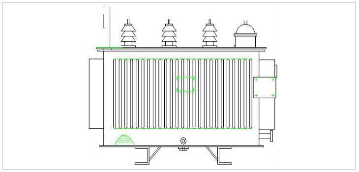
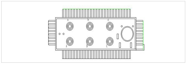
Shape and weight
The outside view
The layout of the bench
The dimensions and weight and part of the specifications (for reference only, the actual weight shall prevail).
The contents which are shown in Table 1 shall be for reference only, and the specific dimensions are shown in the factory drawings.
|
Capacity (kVA) |
External dimensions |
Track gauge (mm) |
Total weight (kg) |
|
630 |
1760 X 970 X 1240 |
660 X 660 |
1235kg |
|
1000 |
2050 X 1020 X 1400 |
660 X 660 |
1220kg |
|
1500 |
2050 X 1020 X 1400 |
660 X 660 |
2083kg |
|
2000 |
2050 X 1000 X 1440 |
660 X 660 |
2120kg |
|
3000 |
2370 X 1120 X 1950 |
1070 X 1070 |
2230kg |
|
3600 |
2650 X 1120 X 1830 |
1070 X 1070 |
2900kg |
|
4000 |
2600 X 1120 X 2075 |
1070 X 1070 |
3430kg |
|
5000 |
2600 X 1150 X2 085 |
1070X1070 |
4000kg |
|
6300 |
2620 X 1150 X 2440 |
1070 X 1070 |
3430kg |
Product Consultation
If you have any interest in our products, please feel free to leave us your intention information
2726472126
Feidong Economic Development Zone LiuZi Road, Anhui Hefei,China

Copyright © 2020 Anhui Zonsen Electric Power Technology Co,Ltd. Powered by www.300.cn 皖ICP备18026616号