
 中文版
中文版
High-voltage passive filter device
Product description
HZSBKLFC high-voltage passive filter device is the best device to control the harmonic in the power supply system. The device is mainly used for controlling the harmonics and at the same time carrying out the reactive power compensation. It can be widely used in the occasions where the harmonic pollution is severe, such as the metallurgy industry, the petrochemical industry, the mining industry, the building material industry and the water supply and drainage systems. The device is composed of the filtration capacitors which are mounted in series with the filtration electric reactors. The device generates the capacitive reactive power at the fundamental frequency, makes compensation for the inductive reactive power in the system and improves the power factor of the system. At the harmonic frequency, the capacitors and the electric reactors generate series resonance, forming a low-impedance path for the harmonic current. In this way, most of the harmonic current is caused to flow into the harmonic filter. The equipment mainly includes the single tuning filtration circuit and the high-pass filtration circuit, which are installed on the side of the 6kV, 10kV and 35kV bus. As the result, the harmonics can be completely or largely absorbed. In this way, a good electric environment is maintained and the safe operation of the electrical equipment is ensured. At the same time, the power factor of the power grid can be improved, and good economic benefit is received.
Model description
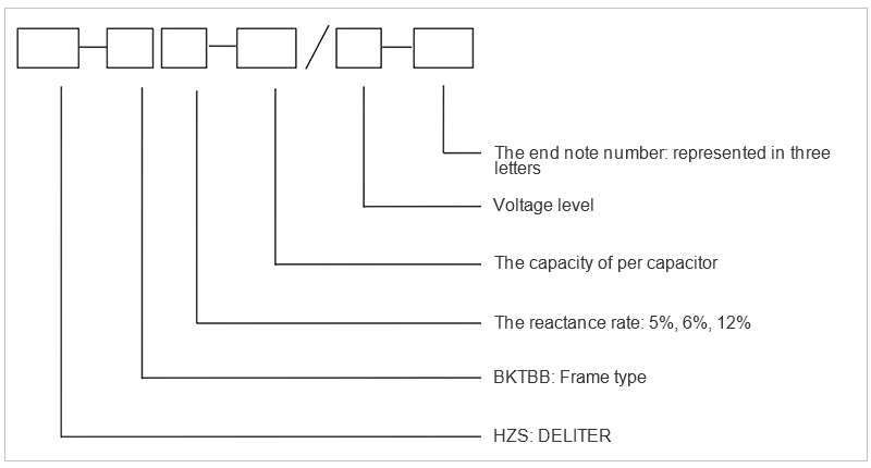
Note:
The first letter: It indicates the connection mode; the second letter: t represents the protection mode of the capacitor bank; the third letter: It indicates the occasion where it is intended to be used.
|
|
The first letter |
The second letter |
The third letter |
||||
|
Letter |
A |
B |
C |
K |
L |
W |
N |
|
Meaning |
Single star type |
Double star type |
Voltage differential protection |
Open triangle voltage protection |
Unbalanced current protection |
Outdoors |
Indoor |
Product features
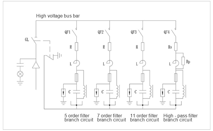
1: The filters consist of a tuned series filter circuit or a second-order high-pass filter circuit, which provides a low impedance channel outside the power grid. This can cause most of these harmonic currents to flow into the filter.
2: The special capacitors and electric reactors are used.
3: The filter branch circuit also provides the power frequency reactive power compensation power.
4: The principle of first switching in and later switching off has been adopted in switching on and switching off of the filter. This can prevent against harmonic amplification and the resonance with the power grid and improve the voltage quality of the power grid.
5: Based on the powerful system design ability of the company, the domestic advanced simulation system has been used to carry out the system simulation. By means of the accurate simulation model, the best design scheme has been determined in an accurate manner. In this way, any problems related to the perplexing harmonics can be solved for the users.
6: Adopting of the microcomputer protection system has made the equipment safe and reliable. The equipment has the overvoltage protection, the undervoltage protection, the undercurrent protection, the overcurrent protection, the zero sequence current protection, as well as the unbalanced voltage protection with up to four capacitor branch circuits.
7: Two control modes are available, that is, the manual control mode and the automatic control mode. So the operations are convenient and reliable and a high degree of intelligence has been provided.
Product primary system diagram
Conditions of use
I. Working environment and conditions
a. The outdoor ambient temperature: -35℃ ~ +45℃
b. The relative humidity in the ambient air: It shall be between 20% and 90% at 40℃.
c.The atmospheric pressure: The altitude shall be 2000 meters and below.
II. The requirements for the surrounding environmental
a. Strong vibrations and shocks shall not be allowed;
b. No corrosive and destructive gases, conductive media, media which contain any explosive dangerous shall be allowed, and serious mold shall not be allowed.
Main technical parameters
1: The rated voltage level: 6, 10, 35 kV; the rated frequency: 50 Hz.
2: The maximum operating voltage: 6.6, 12, 40.5 kV; the maximum insulation level: 23, 30, 75 kV.
3: The rated capacity: 100-10000 kvar, which can be divided into 1 group and 4 groups.
4: The filtering effect: The total distortion rate of voltage harmonics is less than 4%, the filtering rate of current harmonics is more than 70%; The compensation effect : the power factor is more than 0.9.
5: The device can carry out operation for a long period of time at a voltage which is 1.1 times as high as the rated working voltage.
6. The device can perform running continuously under an over-current whose square mean root does not exceed 1.3 times the rated current of the capacitor.
7. Each capacitor is equipped with a discharge coil, which can reduce the remaining voltage to below 50 V in 30 seconds.
8: The difference between the total value of the actually measured capacities of all the capacitors and the total value of the rated capacity of each capacitor shall not exceed + 10%--0, and the deviations in the capacitance of the phases shall not exceed 5%.
Product selection
|
No. |
Excessive harmonic(times) |
Model and specification |
Quantity of branch circuits |
Rated voltage (kV) |
Rated voltage of capacitor bank (kV) |
Reactance rate (%) |
|
1 |
5 |
5 times of single tuning |
1 |
6/10 |
7.8/12 |
4.8 |
|
2 |
7 |
7 times of single tuning |
1 |
6/10 |
7.4/12 |
6.7 |
|
3 |
11 |
11 times of single tuning |
1 |
6/10 |
7.2/12 |
10.5 |
|
4 |
5+7 |
5 times of single tuning + 7 times of high-pass tuning |
2 |
6/10 |
7.8/12+7.4/12 |
|
|
5 |
11+13 |
11times of single tuning + 13 times of high-pass tuning |
2 |
6/10 |
7.2/12+7.0/12 |
|
|
6 |
5+7+11 |
5 times of single tuning + 7 times of single tuning + 11 times of high-pass tuning |
3 |
6/10 |
7.8/12+7.4/12+7.2/12 |
|
|
7 |
5+7+11+13 |
5 times of single tuning + 7 times of single tuning + 13 times of high-pass tuning |
4 |
6/10 |
7.8/12+7.4/12+7.2/12+7.0/12 |
|
Ordering instruction
1: The compensation capacities and the number of the compensation passages stated in the above shall be subjected to modifications depending on the customer needs.
2: For the capacity, only 10008kvar is listed in the above table. The excessive compensation capacities and the excessive number of the compensation passages can be customized according to the customer needs
3: The harmonic situation listed above in the case of the typical six-pulse rectification or twelve-pulse rectification, which can cover most of the operating state of the system. In case that any different operating states are necessary, it can be customized according to the field situation.
4: The design of the filter branch circuits shall be based on the harmonic data obtained in the field.
5: At the time of making an order, the customer shall need to provide the content of the harmonic system, the nature of the system loads as well as the capacity of the system.
The mode of installation:
The equipment shall be applicable for both indoor installation and the outdoor installation.
Product Consultation
If you have any interest in our products, please feel free to leave us your intention information
2726472126
Feidong Economic Development Zone LiuZi Road, Anhui Hefei,China

Copyright © 2020 Anhui Zonsen Electric Power Technology Co,Ltd. Powered by www.300.cn 皖ICP备18026616号